Journals > > Topics > Optical Device
Optical Device|40 Article(s)
Boundary Layer Effect Simulation Based on Liquid Crystal Spatial Light Modulator
Gang JING, Zhi LIU, Peng LIN, Shutong LIU, and Qingfang JIANG
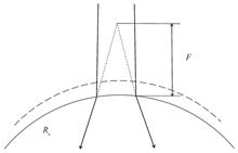
With the advancement of flight conditions for aerospace platforms, the impact of the boundary layer effect on space laser communication transmission is also growing. In order to reduce the influence of the boundary layer effect, corresponding correction methods must be studied. To provide verification conditions for the boundary layer effect correction system of laser communication on aerospace platforms, a simulator based on the Liquid Crystal Spatial Light Modulator (LC-SLM) was designed to simulate the boundary layer effect. This article first analyzes it from the perspective of geometric optics. It is assumed that the boundary layer is a thin layer (the inner and outer diameters are equal). The refractive index of the free flow is different from the refractive index of the boundary layer. Substituting them into the focal length formula of the lens makes it equivalent to a negative lens. Under different flight conditions, the focal length of the equivalent lens is different. Then use computer software to perform numerical analysis. Setting the wall curvature radius of the aerodynamic platform as 190 mm and the flight Mach number range as 0~5 Ma, in the case of troposphere (0~11 km), lower stratosphere (11~20 km), and upper stratosphere (20~32 km), the relationship curves are obtained between the Mach number, flight altitude, and the equivalent focal length of the negative lens representing the boundary layer effect. Research shows that as the Mach number increases, the equivalent focal length of the negative lens decreases, indicating a greater impact on the communication beam. Especially when the Mach number is small, the equivalent lens focal length changes more significantly with the Mach number. After that, the changes stabilized. In terms of flight altitude, the higher the flight altitude, the thinner the air and the lower the temperature, the boundary layer effect decreases accordingly until the equivalent lens focal length value approaches infinity, at which point it can basically be ignored.Based on the above analysis, the following is an introduction to the boundary layer simulation equipment. The core device of this simulator is the LC-SLM. The phase modulation grayscale image is obtained from the phase distribution function of the lens. The grayscale information controls the applied voltage of the LC-SLM, thereby controlling the deflection of the liquid crystal molecules in the LC-SLM, thereby affecting the response to light phase modulation. Load phase grayscale images of different focal lengths into the LC-SLM to realize the function of the zoom lens, and change the focal length of the simulated zoom lens to simulate the boundary layer effect under different flight conditions of the aviation platform. Due to the LC-SLM modulation depth is not an ideal 2π, and the relationship between the modulation depth and the loaded gray value is not an ideal mapping, the designed focal length value of the simulated zoom lens is inconsistent with the actual focal length value. Therefore, it is necessary to design and build an experimental platform to verify the accuracy of its simulation. This experiment uses a 1 550 nm laser as the light source, and emits parallel light after passing through the collimated beam expansion system. Since LC-SLM can only modulate linearly polarized light, a polarizer is added in front, and then enters the LC-SLM. The phase grayscale images of the lens focal lengths corresponding to the ten types of boundary layer effects in flight states are loaded into the LC-SLM respectively, and finally an infrared camera is used to receive and collect light spots at a close distance. There is a lot of noise in the original spot image, which will affect the accuracy of the spot size analysis. Therefore, the obtained original spot image is sequentially subjected to brightness adjustment, median filtering, threshold segmentation, morphological processing and edge coordinate extraction, and Hough transform circle fitting is used to obtain the spot centroid position and spot radius. Due to limitations of computer memory and computing power, the calculation accuracy is 0.05 pixel values. Then make an error line chart between the actual spot radius value of these ten sets of data and the theoretically calculated spot radius value. The calculated root mean square error is 0.043 75. This experiment verified the feasibility and effectiveness of the proposed boundary layer simulation method. With the advancement of flight conditions for aerospace platforms, the impact of the boundary layer effect on space laser communication transmission is also growing. In order to reduce the influence of the boundary layer effect, corresponding correction methods must be studied. To provide verification conditions for the boundary layer effect correction system of laser communication on aerospace platforms, a simulator based on the Liquid Crystal Spatial Light Modulator (LC-SLM) was designed to simulate the boundary layer effect. This article first analyzes it from the perspective of geometric optics. It is assumed that the boundary layer is a thin layer (the inner and outer diameters are equal). The refractive index of the free flow is different from the refractive index of the boundary layer. Substituting them into the focal length formula of the lens makes it equivalent to a negative lens. Under different flight conditions, the focal length of the equivalent lens is different. Then use computer software to perform numerical analysis. Setting the wall curvature radius of the aerodynamic platform as 190 mm and the flight Mach number range as 0~5 Ma, in the case of troposphere (0~11 km), lower stratosphere (11~20 km), and upper stratosphere (20~32 km), the relationship curves are obtained between the Mach number, flight altitude, and the equivalent focal length of the negative lens representing the boundary layer effect. Research shows that as the Mach number increases, the equivalent focal length of the negative lens decreases, indicating a greater impact on the communication beam. Especially when the Mach number is small, the equivalent lens focal length changes more significantly with the Mach number. After that, the changes stabilized. In terms of flight altitude, the higher the flight altitude, the thinner the air and the lower the temperature, the boundary layer effect decreases accordingly until the equivalent lens focal length value approaches infinity, at which point it can basically be ignored.Based on the above analysis, the following is an introduction to the boundary layer simulation equipment. The core device of this simulator is the LC-SLM. The phase modulation grayscale image is obtained from the phase distribution function of the lens. The grayscale information controls the applied voltage of the LC-SLM, thereby controlling the deflection of the liquid crystal molecules in the LC-SLM, thereby affecting the response to light phase modulation. Load phase grayscale images of different focal lengths into the LC-SLM to realize the function of the zoom lens, and change the focal length of the simulated zoom lens to simulate the boundary layer effect under different flight conditions of the aviation platform. Due to the LC-SLM modulation depth is not an ideal 2π, and the relationship between the modulation depth and the loaded gray value is not an ideal mapping, the designed focal length value of the simulated zoom lens is inconsistent with the actual focal length value. Therefore, it is necessary to design and build an experimental platform to verify the accuracy of its simulation. This experiment uses a 1 550 nm laser as the light source, and emits parallel light after passing through the collimated beam expansion system. Since LC-SLM can only modulate linearly polarized light, a polarizer is added in front, and then enters the LC-SLM. The phase grayscale images of the lens focal lengths corresponding to the ten types of boundary layer effects in flight states are loaded into the LC-SLM respectively, and finally an infrared camera is used to receive and collect light spots at a close distance. There is a lot of noise in the original spot image, which will affect the accuracy of the spot size analysis. Therefore, the obtained original spot image is sequentially subjected to brightness adjustment, median filtering, threshold segmentation, morphological processing and edge coordinate extraction, and Hough transform circle fitting is used to obtain the spot centroid position and spot radius. Due to limitations of computer memory and computing power, the calculation accuracy is 0.05 pixel values. Then make an error line chart between the actual spot radius value of these ten sets of data and the theoretically calculated spot radius value. The calculated root mean square error is 0.043 75. This experiment verified the feasibility and effectiveness of the proposed boundary layer simulation method.
Acta Photonica Sinica
- Publication Date: Feb. 25, 2024
- Vol. 53, Issue 2, 0223001 (2024)


Non-volatile Photonic Multilevel Devices Based on Phase Change Materials
Bing SONG, Jinrong WANG, Hengyu ZHANG, Zhenyuan SUN, and Qingjiang LI
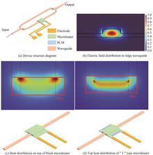
The rapid development of artificial intelligence has posed new and higher demands on computing systems. Electronic computing systems, represented by Graphics Processors Unit(GPU), adopt the von Neumann architecture, which results in frequent data migration and high energy consumption due to the separation of processors and memory. The parasitic capacitance in electronic computing systems also hinders further improvement in computing speed, making it unable to meet the needs of further development of artificial intelligence for high-speed and high-efficiency computing hardware. The rapid development of integrated photonic devices has provided a feasible solution for achieving high-speed and high-efficiency computing hardware. The tunable multivalued devices based on Mach-Zehnder interferometers are a major technological approach in constructing photonic intelligent accelerators. These devices have the advantages of wide bandwidth and temperature insensitivity, making them an excellent choice for photonic hardware accelerators. Phase-change materials have the characteristics of continuously adjustable refractive index and non-volatile retention. Combining phase-change materials with Mach-Zehnder interferometers can achieve non-volatile multivalued properties, providing a new device foundation for constructing photonic intelligent accelerators. In this paper, a non-volatile photonic multivalued device with an Indium Tin Oxides (ITO) microheater is designed based on the combination of phase-change materials and Mach-Zehnder interferometer modulators. First, the structure of the photonic multivalued device is designed. Sb2Se3 is chosen as the phase-change material, and ITO is selected as the microheater material. The Sb2Se3 is deposited on one arm of the Mach-Zehnder interferometers waveguide, and ITO is deposited on top of the Sb2Se3. Cr/Au is deposited at the edge of the ITO to form electrodes. When the state of Sb2Se3 changes, it affects the phase of the transmitted light on the Mach-Zehnder interferometers waveguide, thereby changing the output of the Mach-Zehnder interferometers. This scheme has the advantages of faster modulation speed and higher modulation precision, enabling state transitions of the device to be achieved in milliseconds. The thermal distribution of the microheater has an important influence on the phase transition of the phase-change material. Two different microheater structures are designed and simulated using COMSOL software, including a square-shaped ITO and a structure with wider edges and a narrower middle. Through electrical-thermal simulations, it is found that the second structure can concentrate the generated heat more effectively and improve the efficiency of the microheater. Furthermore, the length and thickness parameters of Sb2Se3 are optimized through simulations in Lumerical software. Lengths ranging from 20 μm to 50 μm and thicknesses ranging from 10 nm to 40 nm are chosen. Finally, a length of 30 μm and a thickness of 30nm are determined as the optimal parameters for Sb2Se3, which maximize the modulation window of the device. The device is fabricated using processes such as photolithography, magnetron sputtering, and inductively coupled plasma etching. During the testing process, electrical pulses are applied to the microheater, with a pulse width of 1ms and an amplitude of 13.4 V. The tests demonstrate that the device achieves multivalued modulation with over 32 states (5 bits) during the application of electrical pulses. Several states are also selected for the retention characteristic tests, which show that the device can maintain stable states for up to 20 minutes, indicating good non-volatility. Finally, the spectral characteristics of the photonic multivalued device are tested to determine its bandwidth. The tests show that the output of the device remains stable between 1 540 nm and 1 580 nm, indicating certain broadband characteristics and providing a foundation for parallel computing. This electrically modulated non-volatile photonic multivalued device serves as a fundamental unit for large-scale non-volatile reconfigurable photonic hardware neural networks. In the future, the performance of this device can be further improved by exploring new microheater designs, aiming for lower power consumption and more adjustable states in photonic multivalued devices. The rapid development of artificial intelligence has posed new and higher demands on computing systems. Electronic computing systems, represented by Graphics Processors Unit(GPU), adopt the von Neumann architecture, which results in frequent data migration and high energy consumption due to the separation of processors and memory. The parasitic capacitance in electronic computing systems also hinders further improvement in computing speed, making it unable to meet the needs of further development of artificial intelligence for high-speed and high-efficiency computing hardware. The rapid development of integrated photonic devices has provided a feasible solution for achieving high-speed and high-efficiency computing hardware. The tunable multivalued devices based on Mach-Zehnder interferometers are a major technological approach in constructing photonic intelligent accelerators. These devices have the advantages of wide bandwidth and temperature insensitivity, making them an excellent choice for photonic hardware accelerators. Phase-change materials have the characteristics of continuously adjustable refractive index and non-volatile retention. Combining phase-change materials with Mach-Zehnder interferometers can achieve non-volatile multivalued properties, providing a new device foundation for constructing photonic intelligent accelerators. In this paper, a non-volatile photonic multivalued device with an Indium Tin Oxides (ITO) microheater is designed based on the combination of phase-change materials and Mach-Zehnder interferometer modulators. First, the structure of the photonic multivalued device is designed. Sb2Se3 is chosen as the phase-change material, and ITO is selected as the microheater material. The Sb2Se3 is deposited on one arm of the Mach-Zehnder interferometers waveguide, and ITO is deposited on top of the Sb2Se3. Cr/Au is deposited at the edge of the ITO to form electrodes. When the state of Sb2Se3 changes, it affects the phase of the transmitted light on the Mach-Zehnder interferometers waveguide, thereby changing the output of the Mach-Zehnder interferometers. This scheme has the advantages of faster modulation speed and higher modulation precision, enabling state transitions of the device to be achieved in milliseconds. The thermal distribution of the microheater has an important influence on the phase transition of the phase-change material. Two different microheater structures are designed and simulated using COMSOL software, including a square-shaped ITO and a structure with wider edges and a narrower middle. Through electrical-thermal simulations, it is found that the second structure can concentrate the generated heat more effectively and improve the efficiency of the microheater. Furthermore, the length and thickness parameters of Sb2Se3 are optimized through simulations in Lumerical software. Lengths ranging from 20 μm to 50 μm and thicknesses ranging from 10 nm to 40 nm are chosen. Finally, a length of 30 μm and a thickness of 30nm are determined as the optimal parameters for Sb2Se3, which maximize the modulation window of the device. The device is fabricated using processes such as photolithography, magnetron sputtering, and inductively coupled plasma etching. During the testing process, electrical pulses are applied to the microheater, with a pulse width of 1ms and an amplitude of 13.4 V. The tests demonstrate that the device achieves multivalued modulation with over 32 states (5 bits) during the application of electrical pulses. Several states are also selected for the retention characteristic tests, which show that the device can maintain stable states for up to 20 minutes, indicating good non-volatility. Finally, the spectral characteristics of the photonic multivalued device are tested to determine its bandwidth. The tests show that the output of the device remains stable between 1 540 nm and 1 580 nm, indicating certain broadband characteristics and providing a foundation for parallel computing. This electrically modulated non-volatile photonic multivalued device serves as a fundamental unit for large-scale non-volatile reconfigurable photonic hardware neural networks. In the future, the performance of this device can be further improved by exploring new microheater designs, aiming for lower power consumption and more adjustable states in photonic multivalued devices.
Acta Photonica Sinica
- Publication Date: Jan. 25, 2024
- Vol. 53, Issue 1, 0123001 (2024)
Design Photonic Crystal All-optical Logic Gates Using Machine Learning
Jianwei CHEN, Ran HAO, Chunlian ZHAN, Shangzhong JIN, Pengju ZHANG, Xingang ZHUANG, and Feng FEI
The all-optical logic gate is the core component of the photonic computer, optical signal processing, and all-optical network. Based on the photonic crystal, the all-optical logic gate has attracted much attention due to its simple structure, low loss, fast operation speed, and small volume. Photonic crystal waveguides can manipulate light for logical operations, which may open up new prospects for photonic computing and optical interconnection networks. However, the design of photonic crystal logic gates is still an iterative process, and the reverse acquisition of geometric structures according to requirements is the key to solving practical engineering problems. To accelerate the performance analysis of photonic crystals and the design of all-optical logic gates, a neural network design of bandgap transmission photonic crystal all-optical logic gates was proposed. In this study, TensorFlow was used as the development framework of the neural network, and a forward performance characterization and inverse structure prediction model of the photonic crystal waveguide was constructed: the forward performance characterization model had 13 fully connected layers, and the total number of parameters trained by the neural network was 197 612, which can realize the timely prediction of the structure of the photonic crystal waveguide to the optical performance; the inverse structure prediction model had 26 fully connected layers, and the total number of parameters trained by the neural network was 155 704, which could reversely design the structure parameters of the photonic crystal waveguide according to the required optical performance, which is helpful to solve practical engineering problems. The Intel Core i9-10940X processor and RTX 3080 Ti graphics card are used for the forward performance characterization and reverse structure prediction network, with training times of 0.2 and 0.36 hours, respectively. The coefficient of determination between the predicted and actual values of the computational neural network was 0.997 for the forward neural network and 0.998 for the inverse network, which shows that the predicted value is very close to the actual value, demonstrating the accuracy of the network. In addition, using the inverse neural network, the structure parameters of the photonic crystal logic gate were successfully predicted according to the required optical properties, such as group index, photonic bandgap, and working wavelength. This logic gate uses gap soliton transmission. When the frequency of the input signal is at the edge of the photonic gap, the output port of the logic gate is nonlinearly disturbed by other input signals. By controlling the frequency and amplitude of the input pulse, the angular frequency displacement caused by the Kerr nonlinearity can be controlled, thus realizing logical operation. The time-domain finite difference method is used to simulate the AND and NOT operations of the all-optical logic gate. The period of the photonic crystal logic gate is 420 nm, and the output port is 70 periods away from the input port. The logic gate performed AND and NOT operations on the Gaussian pulse input signals of“10”and“11”in the time domain, and the output pulse signals of AND and NOT were detected as“10”and“01”, respectively, demonstrating the accuracy of the logic gate. Compared with the input pulse and the output pulse of the AND operation, the pulse width of the input signal was 10 ps, and the output signal was 10.36 ps, with a change of 3.6%. Moreover, when the input pulse intensity was reduced to 1/e, the original pulse width was 5.82 ps, and the output pulse of the logic operation was 5.88 ps, with a change of 1%. This logic gate can achieve stable envelope logic operation in the time domain. The above results show that the use of machine learning to design photonic crystal all-optical logic gates are expected to be applied to the design and optimization of ultra-compact nonlinear optical devices. The all-optical logic gate is the core component of the photonic computer, optical signal processing, and all-optical network. Based on the photonic crystal, the all-optical logic gate has attracted much attention due to its simple structure, low loss, fast operation speed, and small volume. Photonic crystal waveguides can manipulate light for logical operations, which may open up new prospects for photonic computing and optical interconnection networks. However, the design of photonic crystal logic gates is still an iterative process, and the reverse acquisition of geometric structures according to requirements is the key to solving practical engineering problems. To accelerate the performance analysis of photonic crystals and the design of all-optical logic gates, a neural network design of bandgap transmission photonic crystal all-optical logic gates was proposed. In this study, TensorFlow was used as the development framework of the neural network, and a forward performance characterization and inverse structure prediction model of the photonic crystal waveguide was constructed: the forward performance characterization model had 13 fully connected layers, and the total number of parameters trained by the neural network was 197 612, which can realize the timely prediction of the structure of the photonic crystal waveguide to the optical performance; the inverse structure prediction model had 26 fully connected layers, and the total number of parameters trained by the neural network was 155 704, which could reversely design the structure parameters of the photonic crystal waveguide according to the required optical performance, which is helpful to solve practical engineering problems. The Intel Core i9-10940X processor and RTX 3080 Ti graphics card are used for the forward performance characterization and reverse structure prediction network, with training times of 0.2 and 0.36 hours, respectively. The coefficient of determination between the predicted and actual values of the computational neural network was 0.997 for the forward neural network and 0.998 for the inverse network, which shows that the predicted value is very close to the actual value, demonstrating the accuracy of the network. In addition, using the inverse neural network, the structure parameters of the photonic crystal logic gate were successfully predicted according to the required optical properties, such as group index, photonic bandgap, and working wavelength. This logic gate uses gap soliton transmission. When the frequency of the input signal is at the edge of the photonic gap, the output port of the logic gate is nonlinearly disturbed by other input signals. By controlling the frequency and amplitude of the input pulse, the angular frequency displacement caused by the Kerr nonlinearity can be controlled, thus realizing logical operation. The time-domain finite difference method is used to simulate the AND and NOT operations of the all-optical logic gate. The period of the photonic crystal logic gate is 420 nm, and the output port is 70 periods away from the input port. The logic gate performed AND and NOT operations on the Gaussian pulse input signals of“10”and“11”in the time domain, and the output pulse signals of AND and NOT were detected as“10”and“01”, respectively, demonstrating the accuracy of the logic gate. Compared with the input pulse and the output pulse of the AND operation, the pulse width of the input signal was 10 ps, and the output signal was 10.36 ps, with a change of 3.6%. Moreover, when the input pulse intensity was reduced to 1/e, the original pulse width was 5.82 ps, and the output pulse of the logic operation was 5.88 ps, with a change of 1%. This logic gate can achieve stable envelope logic operation in the time domain. The above results show that the use of machine learning to design photonic crystal all-optical logic gates are expected to be applied to the design and optimization of ultra-compact nonlinear optical devices.
Acta Photonica Sinica
- Publication Date: Sep. 25, 2023
- Vol. 52, Issue 9, 0923003 (2023)
Multifunctional Device Design Based on Composite Gratings and Gradient Supersurfaces
Hai LIU, Siyi ZHAO, Cong CHEN, Peng GAO, Yaowei DAI, Jiaming ZHAO, Yinhui WAN, Xiangyu LU, Xinyan WANG, and Lei LI
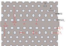
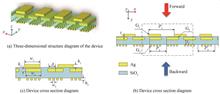
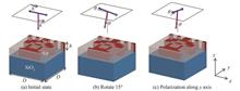
Most of the current research can only realize the asymmetric transmission of light singly, in the face of the demand for multifunctional application scenarios, the design of multifunctional integrated devices has become a development trend. Therefore, the combination of grating and super-surface, which can realize different functions in different incidence and polarization states, is a multifunctional device combining a metal/medium/metal composite grating and a gradient super-surface structure. The asymmetric transmission of light is realized through the asymmetric structure of the composite grating, and when the modulated wave vector matches the wave vector of the Surface Plasmon Polaritons (SPPs), the SPPs excited by the metal grating produce single-band light transmission, and the anomalous reflection of light is realized through the gradient hypersurface. When an x-polarized light wave is incident, the SPPs are unidirectionally excited at 1 550 nm in the forward-incidence direction, and the forward transmittance at this wavelength is up to 0.9. In the reverse-incidence direction, the SPPs are unidirectionally excited at 1 128 nm, and the backward transmittance at this wavelength is up to 0.86. Due to the different periods of the upper and lower gratings and the difference in permittivity at the incident interfaces, the surface-iso-polarized excitations can be excited in a single-band light transmission. The upper and lower gratings cannot excite SPPs in the same band at different incidence directions, and the reverse transmission is suppressed in the forward excitation band and vice versa. In order to obtain the best performance of the asymmetric transmission characteristics, the parameters of the device are optimized to enhance the interaction between the beam and the grating. The effect of the grating transverse position on the transmission spectrum is investigated. Changes in the grating transverse position alter the strength of the coupling effect, leading to the splitting of the transmission peaks, the emergence of double peaks or even multiple peaks, and the broadening of the transmission spectrum, and the effective refractive index of the double-layered grating and the relative phases of the light passing through the sub-wavelength grooves of the two gratings are also varied, leading to changes in the resonance wavelengths and the transmission spectra. The changes in the transmission spectra of the upper and lower metal gratings and the intermediate SiO2 film under different parameters are also investigated. In addition, in the direction of reverse incidence, the device exhibits zero absorption in the entire band from 1 300 to 1 400 nm, and the reflectivity is greater than 0.9, which can be used as a reflector. In order to verify that the asymmetric transmission phenomenon occurs only when x-polarized light waves are incident, the transmission spectra of y-polarized light waves incident on the device in different incident directions are also simulated, and it is found that the device does not exhibit asymmetric transmission when y-polarized light waves are incident, due to the fact that the SPPs field component reaches its maximum at the metal/dielectric boundary, and decays exponentially in the dielectrics at the two ends of the metal. In visible and infrared light, the real part of the permittivity of most metals is negative, so that the permittivity of the metal is different from that of the surrounding permittivity, and only light waves in the x-polarized state can efficiently excite the SPPs. Given that the asymmetric transmission properties and reflection properties of gratings at the incidence of light waves in the x-polarized state have been extensively studied, the anomalous reflections are achieved by irradiating the underlying phase-gradient hypersurfaces with light from the other wavelength band in order to realize the versatility of the device. When the y-polarized state light wave is incident, in the reverse incidence direction, the light directly irradiates the phase gradient super-surface, and according to the Generalized Snell's Law, in order to form a phase discontinuous super-surface to make the length of the underlying Ag nanostructures of each unit structure in the super-unit is different, which forms the reflective phase delay, and produces the phenomenon of anomalous reflections when the light is irradiated. To solve the problem of asymmetric transmission and single function of anomalous reflection devices, unidirectional excitation of SPPs and the Generalized Snell's Law are combined to realize multifunctionality, which provides a reference for a variety of polarization-related multifunctional devices and integrated optical components. Most of the current research can only realize the asymmetric transmission of light singly, in the face of the demand for multifunctional application scenarios, the design of multifunctional integrated devices has become a development trend. Therefore, the combination of grating and super-surface, which can realize different functions in different incidence and polarization states, is a multifunctional device combining a metal/medium/metal composite grating and a gradient super-surface structure. The asymmetric transmission of light is realized through the asymmetric structure of the composite grating, and when the modulated wave vector matches the wave vector of the Surface Plasmon Polaritons (SPPs), the SPPs excited by the metal grating produce single-band light transmission, and the anomalous reflection of light is realized through the gradient hypersurface. When an x-polarized light wave is incident, the SPPs are unidirectionally excited at 1 550 nm in the forward-incidence direction, and the forward transmittance at this wavelength is up to 0.9. In the reverse-incidence direction, the SPPs are unidirectionally excited at 1 128 nm, and the backward transmittance at this wavelength is up to 0.86. Due to the different periods of the upper and lower gratings and the difference in permittivity at the incident interfaces, the surface-iso-polarized excitations can be excited in a single-band light transmission. The upper and lower gratings cannot excite SPPs in the same band at different incidence directions, and the reverse transmission is suppressed in the forward excitation band and vice versa. In order to obtain the best performance of the asymmetric transmission characteristics, the parameters of the device are optimized to enhance the interaction between the beam and the grating. The effect of the grating transverse position on the transmission spectrum is investigated. Changes in the grating transverse position alter the strength of the coupling effect, leading to the splitting of the transmission peaks, the emergence of double peaks or even multiple peaks, and the broadening of the transmission spectrum, and the effective refractive index of the double-layered grating and the relative phases of the light passing through the sub-wavelength grooves of the two gratings are also varied, leading to changes in the resonance wavelengths and the transmission spectra. The changes in the transmission spectra of the upper and lower metal gratings and the intermediate SiO2 film under different parameters are also investigated. In addition, in the direction of reverse incidence, the device exhibits zero absorption in the entire band from 1 300 to 1 400 nm, and the reflectivity is greater than 0.9, which can be used as a reflector. In order to verify that the asymmetric transmission phenomenon occurs only when x-polarized light waves are incident, the transmission spectra of y-polarized light waves incident on the device in different incident directions are also simulated, and it is found that the device does not exhibit asymmetric transmission when y-polarized light waves are incident, due to the fact that the SPPs field component reaches its maximum at the metal/dielectric boundary, and decays exponentially in the dielectrics at the two ends of the metal. In visible and infrared light, the real part of the permittivity of most metals is negative, so that the permittivity of the metal is different from that of the surrounding permittivity, and only light waves in the x-polarized state can efficiently excite the SPPs. Given that the asymmetric transmission properties and reflection properties of gratings at the incidence of light waves in the x-polarized state have been extensively studied, the anomalous reflections are achieved by irradiating the underlying phase-gradient hypersurfaces with light from the other wavelength band in order to realize the versatility of the device. When the y-polarized state light wave is incident, in the reverse incidence direction, the light directly irradiates the phase gradient super-surface, and according to the Generalized Snell's Law, in order to form a phase discontinuous super-surface to make the length of the underlying Ag nanostructures of each unit structure in the super-unit is different, which forms the reflective phase delay, and produces the phenomenon of anomalous reflections when the light is irradiated. To solve the problem of asymmetric transmission and single function of anomalous reflection devices, unidirectional excitation of SPPs and the Generalized Snell's Law are combined to realize multifunctionality, which provides a reference for a variety of polarization-related multifunctional devices and integrated optical components.
Acta Photonica Sinica
- Publication Date: Sep. 25, 2023
- Vol. 52, Issue 9, 0923002 (2023)
Inverse-designed Non-local Metasurface Differentiator
Haoran QIN, Junlong KOU, Jiarong ZHU, Zixin ZHOU, Junzhuan WANG, Zhaoxian CHEN, and Yanqing LU
Differential computing is of great significance for data analysis and processing, especially in image edge recognition and extraction. Edge enhancement technology is particularly useful in compressing data, checking objects for defects, etc., making it a hot research topic in the past decades. Compared with electric circuits, differentiators that use light as the transport carrier have great advantages in terms of speed, dissipation and stability. However, conventional optical dielectric lenses are still inferior in terms of accurate and rapid response due to some reasons, such as non-negligible losses during reflection, aberrations caused by spherical surfaces, diffraction limits of light and more importantly, their bulky geometries. Using sub-wavelength optical metastructures, i.e., two-dimensional artificial structures, can overcome these inherent constraints and enable the implementation of efficient, responsive and miniaturized optical devices. By rationally utilizing rather than suppressing the interaction between the pixels, non-local metasurfaces can greatly reduce the thickness of the structure and the contrast of refractive indexes between different materials. This allows better tailoring of light behaviors as it propagates in a specially designed structure under specific conditions, thus achieving more complex optical functions. Notably, previous researches tend to focus on particular application scenario but ignore the generality. To remedy this shortcoming, here we combine the optimization algorithm with the inverse designing of the optical metasurface. Different operation logics can be achieved by modifying the objective function of the optimization algorithm and using the design steps of associating the operation logic to be implemented with an objective function, optimizing the structure, and verifying functionality. We propose a one-dimensional second-order differentiator by inversely designing the material distribution, leading to a non-local metasurface. The transfer function of the designed structure agrees well with our objective function, i.e., the relationship between incident angle and transmittance satisfies the quadratic function, especially when the incident angle is smaller than 10 degrees. We also design a Laplace transformer to prove the generality of the method. Then, we assess the robustness of the design by calculating the objective function or transfer function after making appropriate changes to the obtained optimal solution and comparing the results before and after the change. Finally, we verify their functionality in identifying image edges by illuminating light waves perpendicular to the objects, and then calculating their transmitted waves. In this way, we prove that the transmitted waves can reflect the profile of incident waves in the corresponding polarization direction. The optimization effect of a one-dimensional second-order differentiator is remarkable that the error between the transfer function of the optimal and theoretical solutions is significantly decreased. When optimizing the Laplace transformer, there is still some deviation between the transfer functions of the optimal solution and the theoretical solutions, which may be a locally optimal solution due to the fast convergence of the algorithm itself. Through verification, we find that the structure we design still hold feature of differentiation. Specifically, we use a hollowed-out silver layer as the barrier between the incident plane wave and the structures arranged by two thousand unit cells. The barrier layer only allows waves with a spatial distribution consistent with pattern“N”to pass through, and the transmitted wave reflects the profile of the special pattern. Therefore, we prove that this method has a strong generality and error tolerance. In addition, this method can be extended to the design of other spatial operations, such as integration or spatial filter. Predictably, this method has great potential for designing optical computing units considering its high tolerance for the algorithm and manufacturing process. Furthermore, we can map all the material distributions and their transfer functions calculated in the iteration process to form a database, with which the optimization efficiency can be further improved. Differential computing is of great significance for data analysis and processing, especially in image edge recognition and extraction. Edge enhancement technology is particularly useful in compressing data, checking objects for defects, etc., making it a hot research topic in the past decades. Compared with electric circuits, differentiators that use light as the transport carrier have great advantages in terms of speed, dissipation and stability. However, conventional optical dielectric lenses are still inferior in terms of accurate and rapid response due to some reasons, such as non-negligible losses during reflection, aberrations caused by spherical surfaces, diffraction limits of light and more importantly, their bulky geometries. Using sub-wavelength optical metastructures, i.e., two-dimensional artificial structures, can overcome these inherent constraints and enable the implementation of efficient, responsive and miniaturized optical devices. By rationally utilizing rather than suppressing the interaction between the pixels, non-local metasurfaces can greatly reduce the thickness of the structure and the contrast of refractive indexes between different materials. This allows better tailoring of light behaviors as it propagates in a specially designed structure under specific conditions, thus achieving more complex optical functions. Notably, previous researches tend to focus on particular application scenario but ignore the generality. To remedy this shortcoming, here we combine the optimization algorithm with the inverse designing of the optical metasurface. Different operation logics can be achieved by modifying the objective function of the optimization algorithm and using the design steps of associating the operation logic to be implemented with an objective function, optimizing the structure, and verifying functionality. We propose a one-dimensional second-order differentiator by inversely designing the material distribution, leading to a non-local metasurface. The transfer function of the designed structure agrees well with our objective function, i.e., the relationship between incident angle and transmittance satisfies the quadratic function, especially when the incident angle is smaller than 10 degrees. We also design a Laplace transformer to prove the generality of the method. Then, we assess the robustness of the design by calculating the objective function or transfer function after making appropriate changes to the obtained optimal solution and comparing the results before and after the change. Finally, we verify their functionality in identifying image edges by illuminating light waves perpendicular to the objects, and then calculating their transmitted waves. In this way, we prove that the transmitted waves can reflect the profile of incident waves in the corresponding polarization direction. The optimization effect of a one-dimensional second-order differentiator is remarkable that the error between the transfer function of the optimal and theoretical solutions is significantly decreased. When optimizing the Laplace transformer, there is still some deviation between the transfer functions of the optimal solution and the theoretical solutions, which may be a locally optimal solution due to the fast convergence of the algorithm itself. Through verification, we find that the structure we design still hold feature of differentiation. Specifically, we use a hollowed-out silver layer as the barrier between the incident plane wave and the structures arranged by two thousand unit cells. The barrier layer only allows waves with a spatial distribution consistent with pattern“N”to pass through, and the transmitted wave reflects the profile of the special pattern. Therefore, we prove that this method has a strong generality and error tolerance. In addition, this method can be extended to the design of other spatial operations, such as integration or spatial filter. Predictably, this method has great potential for designing optical computing units considering its high tolerance for the algorithm and manufacturing process. Furthermore, we can map all the material distributions and their transfer functions calculated in the iteration process to form a database, with which the optimization efficiency can be further improved.
Acta Photonica Sinica
- Publication Date: Sep. 25, 2023
- Vol. 52, Issue 9, 0923001 (2023)

CNN-based Method for Dual-layer Liquid Crystal Displays
Qibin FENG, Xin ZHANG, Chen ZHENG, Zi WANG, and Guoqiang LV
Liquid crystal displays (LCDs) have been widely used in consumer electronics, industrial control, medical equipment and other fields. However, the LC panel can not completely block the light from the backlight unit when displaying a black field, resulting in a low Contrast Ratio (CR). There are two techniques to improve CR, including dynamic dimming and dual-layer display. Dynamic dimming technology dynamically adjusts the backlight brightness and pixel grayscales according to the displayed image. At present, dynamic dimming technology is mainly divided into global dimming technology and local dimming technology. CR is proportional to the number of backlight partitions, but the number of backlight partitions is usually much smaller than the number of pixels on the LC panel, resulting in the inability of this technology to achieve pixel-level dimming. The more partitions, the higher the production cost. Another technology to improve CR is dual-layer display. Dual-layer display is to add a LC panel between the backlight and the LC panel, which can greatly reduce light leakage. However, as the two layer LC panels are bonded together with Optically Clear Adhesive (OCA), there is a physical gap between them. When the double-layer LCD is working, both the front and rear panels need to display images. If the input image is directly sent to the front and rear panels without processing, the corresponding pixels of the front and rear panels will be offset when viewing the screen off-axis, resulting in a ghost image. To improve the display quality when viewing off-axis, the input image needs to be split and modified. The common method is to blur the image to the rear panel near the backlight unit and compensate for the pixels of the front panel. It is quite simple to realize such a blurring solution, but the final display quality deteriorates because the resolution of the image to the rear panel becomes lower. In order to balance the relationship between viewing angle and display quality, researchers put forward an angle compensation algorithm. The algorithm establishes a mapping matrix to record the position information of each ray, and then obtains two images through an optimization algorithm. The algorithm can present a higher display quality at larger viewing angles. But the processing time is quite long and no real application is possible.Inspired by the successful applications of Convolutional Neural Networks (CNNs) in image restoration, the paper proposes to adopt CNN to optimize the image for dual-panel display in order to reduce processing time and improve high display quality. The network structure includes three parts: preprocessing, feature extraction and reconstruction. For a dual-panel display, it is best that the images viewed at various angles are as the same as the image viewed off-axis. Therefore, in the preprocessing part, the input image is duplicated to create N copies corresponding to the N viewing angles before sending the image to the network. The feature extraction part consists of 8 convolution layers, and the shortcut connection is introduced to create the residual block that can fuse the features from the shallow network. In the reconstruction part, a reconstructed image is constructed by corresponding multiplication of two images with pixel offset at a certain angle. The purpose of network training is to minimize the errors between the reconstructed images at different viewing angles and the original input image. Therefore, the mean square error is used as a loss function, which is especially defined with the consideration of the total differences between the reconstructed images at different viewing angles and the input image. For dual-panel display, ghost may appear when viewing off-axis, which presents worse effects on the images consisting of many textures. The paper therefore creates a dataset for a dual-layer display, which consists of many images such as figures, animals, buildings, and scenery. All the images contain rich texture information.In order to evaluate the proposed CNN for dual-layer display, some existing methods are applied for comparisons, including fuzzy processing algorithm and viewing-angle-compensation algorithm. 5 viewing angles of 0°, 8°, 34°, 45° and 64° are used for evaluation. To quantitatively evaluate the three methods, Peak Signal-to-noise Ratio (PSNR) and Structural Similarity (SSIM) are employed, and the computation time is compared. Compared with fuzzy processing algorithm, the proposed method presents obvious advantages in PSNR, SSIM and computation time. The PSNR and SSIM of the proposed method at the viewing angle of 0°, 18°, 34° and 45° are almost the same as the viewing-angle-compensation algorithm. The PSNRand SSIM of the proposed method at the viewing angle of 64° are lower than viewing-angle-compensation algorithm, but much higher than the fuzzing processing algorithm. When comparing the computation time, the proposed method presents a great improvement over the other two methods. The computation time of the proposed method is 707.13 times and 4.75 times that of the other two methods, which presents strong practicability.The paper proposes a CNN-based method for dual-layer display. The CNN is used to process the input image, and residual blocks are constructed to improve the quality of the output image. The two output images that correspond to the two layers of LC panels of the dual-layer LCD are reconstructed from different viewing angles to compare with other methods in terms of computation time and display quality. The simulation results show that the proposed method improves both computation time and display quality compared to the fuzzy processing algorithm; compared with the viewing-angle-compensation algorithm, it can greatly reduce the computation time. The proposed method for dual-layer display presents the merits of high display quality and short computation time, which presents a good application prospect. Liquid crystal displays (LCDs) have been widely used in consumer electronics, industrial control, medical equipment and other fields. However, the LC panel can not completely block the light from the backlight unit when displaying a black field, resulting in a low Contrast Ratio (CR). There are two techniques to improve CR, including dynamic dimming and dual-layer display. Dynamic dimming technology dynamically adjusts the backlight brightness and pixel grayscales according to the displayed image. At present, dynamic dimming technology is mainly divided into global dimming technology and local dimming technology. CR is proportional to the number of backlight partitions, but the number of backlight partitions is usually much smaller than the number of pixels on the LC panel, resulting in the inability of this technology to achieve pixel-level dimming. The more partitions, the higher the production cost. Another technology to improve CR is dual-layer display. Dual-layer display is to add a LC panel between the backlight and the LC panel, which can greatly reduce light leakage. However, as the two layer LC panels are bonded together with Optically Clear Adhesive (OCA), there is a physical gap between them. When the double-layer LCD is working, both the front and rear panels need to display images. If the input image is directly sent to the front and rear panels without processing, the corresponding pixels of the front and rear panels will be offset when viewing the screen off-axis, resulting in a ghost image. To improve the display quality when viewing off-axis, the input image needs to be split and modified. The common method is to blur the image to the rear panel near the backlight unit and compensate for the pixels of the front panel. It is quite simple to realize such a blurring solution, but the final display quality deteriorates because the resolution of the image to the rear panel becomes lower. In order to balance the relationship between viewing angle and display quality, researchers put forward an angle compensation algorithm. The algorithm establishes a mapping matrix to record the position information of each ray, and then obtains two images through an optimization algorithm. The algorithm can present a higher display quality at larger viewing angles. But the processing time is quite long and no real application is possible.Inspired by the successful applications of Convolutional Neural Networks (CNNs) in image restoration, the paper proposes to adopt CNN to optimize the image for dual-panel display in order to reduce processing time and improve high display quality. The network structure includes three parts: preprocessing, feature extraction and reconstruction. For a dual-panel display, it is best that the images viewed at various angles are as the same as the image viewed off-axis. Therefore, in the preprocessing part, the input image is duplicated to create N copies corresponding to the N viewing angles before sending the image to the network. The feature extraction part consists of 8 convolution layers, and the shortcut connection is introduced to create the residual block that can fuse the features from the shallow network. In the reconstruction part, a reconstructed image is constructed by corresponding multiplication of two images with pixel offset at a certain angle. The purpose of network training is to minimize the errors between the reconstructed images at different viewing angles and the original input image. Therefore, the mean square error is used as a loss function, which is especially defined with the consideration of the total differences between the reconstructed images at different viewing angles and the input image. For dual-panel display, ghost may appear when viewing off-axis, which presents worse effects on the images consisting of many textures. The paper therefore creates a dataset for a dual-layer display, which consists of many images such as figures, animals, buildings, and scenery. All the images contain rich texture information.In order to evaluate the proposed CNN for dual-layer display, some existing methods are applied for comparisons, including fuzzy processing algorithm and viewing-angle-compensation algorithm. 5 viewing angles of 0°, 8°, 34°, 45° and 64° are used for evaluation. To quantitatively evaluate the three methods, Peak Signal-to-noise Ratio (PSNR) and Structural Similarity (SSIM) are employed, and the computation time is compared. Compared with fuzzy processing algorithm, the proposed method presents obvious advantages in PSNR, SSIM and computation time. The PSNR and SSIM of the proposed method at the viewing angle of 0°, 18°, 34° and 45° are almost the same as the viewing-angle-compensation algorithm. The PSNRand SSIM of the proposed method at the viewing angle of 64° are lower than viewing-angle-compensation algorithm, but much higher than the fuzzing processing algorithm. When comparing the computation time, the proposed method presents a great improvement over the other two methods. The computation time of the proposed method is 707.13 times and 4.75 times that of the other two methods, which presents strong practicability.The paper proposes a CNN-based method for dual-layer display. The CNN is used to process the input image, and residual blocks are constructed to improve the quality of the output image. The two output images that correspond to the two layers of LC panels of the dual-layer LCD are reconstructed from different viewing angles to compare with other methods in terms of computation time and display quality. The simulation results show that the proposed method improves both computation time and display quality compared to the fuzzy processing algorithm; compared with the viewing-angle-compensation algorithm, it can greatly reduce the computation time. The proposed method for dual-layer display presents the merits of high display quality and short computation time, which presents a good application prospect.
Acta Photonica Sinica
- Publication Date: Aug. 25, 2023
- Vol. 52, Issue 8, 0823004 (2023)
Erbium-doped Ga2O3 Waveguide for Optical Amplification
Ruixue LIU, Zheng ZHANG, Jian WU, Zhen YANG, Wei WANG, Tengxiu WEI, and Rongping WANG
The commercial success of Erbium-doped Optical Fiber Amplifier (EDFA) is stimulating the development of Erbium-doped Waveguide Amplifier (EDWA) which is expected to play a key component in the long-distance optical communication system in the future due to its compacted volume and low power consuming. Er ions can emit strong light at 1.55 μm that coincides with the optical communication wavelength. Therefore, when Er3+ ions are doped in a compacted waveguide structure, these ions can be excited by pump light to emit near 1.55 μm and thus amplify the signal light. Numerous studies have shown that, the fluorescence performance of Er3+ is closely related to the factors like matrix material, doping method, preparation and annealing conditions. Especially, many available Er3+-doped matrix materials have been studied so far, some of which show good properties in achieving compacted and high-gain waveguides. Among them, Er doped Al2O3 waveguide has been demonstrated to have excellent performance in optical amplification. Ga is located at the same group of Al, and thus gallium oxide (Ga2O3) has similar physical and chemical properties of Al2O3. Meanwhile, Ga2O3 has many unique advantages, such as high Er3+ doping, broad half width of full maximum in photoluminescent peak at 1.55 μm and high refractive index. Therefore, Ga2O3 has the potential to be used as a host material to fabricate planar optical waveguide device for optical amplification, however, there are no such reports in the literature. In this paper, the fabrication and properties of the erbium-doped gallium oxide films are reported. The films are characterized by Scanning Electron Microscopy (SEM) and X-ray Diffraction (XRD). The effect of the Er-doping concentration, thermal annealing temperature and film thickness on the photoluminescence properties are studied. The results show that the films are amorphous even at an annealing temperature up to 600 ℃. The maximum photoluminescence intensity appears in the film prepared at 40 W erbium oxide sputtering power and 600 ℃ annealing temperature. After optimizing the film performance, we start structural design of the Ga2O3 waveguide. Considering the fact that the fluorine-based gas reacts with Ga2O3 to form volatile gas and non-volatile GaFx is easily adhered to the surface of the film that is difficult to be removed, fluorine-based plasma is not effective in etching Ga2O3. On the other hand, direct etching of the materials containing metallic rare earth element usually leads to the aggregation of the residual metallic Er due to the different etching rate between the host materials and Er. Both could result in a very rough etched surface in the waveguide. In order to solve this problem, two kinds of waveguide structures, e.g., erbium-doped Ga2O3 film filled into SiO2 channel and erbium-doped Ga2O3 film coated on the top of the SiO2 ridge waveguide, are designed to avoid the issues caused by direct etching of Er-doped Ga2O3 film. The light field distribution in these two types of waveguides are simulated in order to maximize the interaction between the light and the effective Er-doped area. Then the waveguides are prepared based on the structural parameters from the simulation, the silicon wafer with a 2 μm thick thermally oxidized layer is used to prepare SiO2 channel and ridge structures via lithographing and etching by Ar/CHF3 etching gas, and then Er-doped Ga2O3 film with a thickness of about 400~500 nm is deposited on these structures to get the final waveguide structure. The minimum propagation loss at 1 310 nm is 1.26 dB/cm. In the future, it is expected to optimize the processing conditions of thin films and waveguides and reduce the optical loss, which could provide the possibility for the preparation of erbium-doped waveguide amplifier with better performance. The commercial success of Erbium-doped Optical Fiber Amplifier (EDFA) is stimulating the development of Erbium-doped Waveguide Amplifier (EDWA) which is expected to play a key component in the long-distance optical communication system in the future due to its compacted volume and low power consuming. Er ions can emit strong light at 1.55 μm that coincides with the optical communication wavelength. Therefore, when Er3+ ions are doped in a compacted waveguide structure, these ions can be excited by pump light to emit near 1.55 μm and thus amplify the signal light. Numerous studies have shown that, the fluorescence performance of Er3+ is closely related to the factors like matrix material, doping method, preparation and annealing conditions. Especially, many available Er3+-doped matrix materials have been studied so far, some of which show good properties in achieving compacted and high-gain waveguides. Among them, Er doped Al2O3 waveguide has been demonstrated to have excellent performance in optical amplification. Ga is located at the same group of Al, and thus gallium oxide (Ga2O3) has similar physical and chemical properties of Al2O3. Meanwhile, Ga2O3 has many unique advantages, such as high Er3+ doping, broad half width of full maximum in photoluminescent peak at 1.55 μm and high refractive index. Therefore, Ga2O3 has the potential to be used as a host material to fabricate planar optical waveguide device for optical amplification, however, there are no such reports in the literature. In this paper, the fabrication and properties of the erbium-doped gallium oxide films are reported. The films are characterized by Scanning Electron Microscopy (SEM) and X-ray Diffraction (XRD). The effect of the Er-doping concentration, thermal annealing temperature and film thickness on the photoluminescence properties are studied. The results show that the films are amorphous even at an annealing temperature up to 600 ℃. The maximum photoluminescence intensity appears in the film prepared at 40 W erbium oxide sputtering power and 600 ℃ annealing temperature. After optimizing the film performance, we start structural design of the Ga2O3 waveguide. Considering the fact that the fluorine-based gas reacts with Ga2O3 to form volatile gas and non-volatile GaFx is easily adhered to the surface of the film that is difficult to be removed, fluorine-based plasma is not effective in etching Ga2O3. On the other hand, direct etching of the materials containing metallic rare earth element usually leads to the aggregation of the residual metallic Er due to the different etching rate between the host materials and Er. Both could result in a very rough etched surface in the waveguide. In order to solve this problem, two kinds of waveguide structures, e.g., erbium-doped Ga2O3 film filled into SiO2 channel and erbium-doped Ga2O3 film coated on the top of the SiO2 ridge waveguide, are designed to avoid the issues caused by direct etching of Er-doped Ga2O3 film. The light field distribution in these two types of waveguides are simulated in order to maximize the interaction between the light and the effective Er-doped area. Then the waveguides are prepared based on the structural parameters from the simulation, the silicon wafer with a 2 μm thick thermally oxidized layer is used to prepare SiO2 channel and ridge structures via lithographing and etching by Ar/CHF3 etching gas, and then Er-doped Ga2O3 film with a thickness of about 400~500 nm is deposited on these structures to get the final waveguide structure. The minimum propagation loss at 1 310 nm is 1.26 dB/cm. In the future, it is expected to optimize the processing conditions of thin films and waveguides and reduce the optical loss, which could provide the possibility for the preparation of erbium-doped waveguide amplifier with better performance.
Acta Photonica Sinica
- Publication Date: Aug. 25, 2023
- Vol. 52, Issue 8, 0823003 (2023)
Design of Low Loss Silicon Waveguide Bend with Width and Curvature Variations
Yue ZHOU, Yaohui SUN, Haoyu WU, Mengjia LU, Guohua HU, Binfeng YUN, and Yiping CUI
As a newly-developing direction, integrated optics have played a strong role in promoting astronomy, biosensing, quantum computing, etc. Silicon photonics is very promising since silicon has several metrics, such as transparency in the main communication bands, high refractive index contrast for high density integration, compatibility with Complementary Metal-Oxide-Semiconductor (CMOS) process for volume production and so on. Silicon waveguide bend is one of the important components for silicon photonics. Although the loss of a single silicon waveguide bend is relativelysmall, the accumulative effect in a large-scale integrated optical circuit can enhance the total loss and may lead to a significant deterioration of the device's performance. Usually, increasing the bend radius of silicon waveguide bends can effectively reduce the loss, but this will degrade the integration density of the chip. It is very important to achieve silicon waveguide bends with compact size and low loss simultaneously. Some solutions to achieve this goal for silicon waveguide bends have been proposed, such as introducing deep etching slots or introducing offset on straight optical waveguides, which have small fabrication tolerance and are difficult to fabricate. In contrast, the special curve-based waveguide bend does not require special fabrication processes and has good process compatibility.The Euler curve, as a special curve used in optical waveguide bends, has a gradual change in curvature from 0 to the maximum value. This scheme effectively reduces the mode mismatch loss between a straight optical waveguide and a bent optical waveguide. In addition, the mode evolution within the bent optical waveguide is limited at the same time. Thus, the overall loss of the bent optical waveguide can be optimized well. However, when the curvature of the Euler curve grows to a maximum value, the corresponding radius of curvature reaches a minimum, where a large radiation loss will exist.As known, by widening the width of the waveguide, the confinement of the optical field can be enhanced, which is an effective way to decrease the radiation loss. To achieve a smaller size and a lower loss, two silicon-based single-mode 90° waveguide bend structures based on different inner and outer curves to realize width gradient are proposed in this paper. The waveguide bend Ⅰ consists of a circular inner curve and an Euler-circular outer curve, and the waveguide bend Ⅱ combines an Euler-circular inner curve and an Euler outer curve. On the one hand, according to the variability of the radius of curvature of the inner and outer curves, the curve proportion of the Euler-circular curve can be adjusted by optimizing the design parameters accordingly, making the width inside the waveguide bend changes gradually to effectively reducing the radiation loss. On the other hand, the curvature of an Euler-circular curve or an Euler curve in waveguide bend Ⅰ and Ⅱ increases from zero, which reduces the mode mismatch loss at the connections of the straight optical waveguides and the bent optical waveguides, further decreasing the bending loss. In terms of fabrication, the proposed structure has no special process requirements and is easy to fabricate.The proposed two silicon waveguide bend structures are simulated and optimized by three dimensional finite difference time domain (3D-FDTD) method. The simulation results show that the loss of the waveguide bend I is smaller than those of the circular bend, Euler bend, Euler-circular bend, and Bezier bend when the equivalent bending radius R0 is in the range of 2 to 5 μm. In particular, when R0=2 μm, a silicon waveguide bend with bending loss of only 0.005 6 dB/90° is obtained, and low wavelength dependence of the loss is achieved. When R0=4 μm and 5 μm, the loss of the waveguide bend II is also one order of magnitude lower than the above mentioned waveguide bends. In summary, the proposed silicon waveguide bend Ⅰ and Ⅱ have the advantages of compact size and low loss, which are very promising for future applications in compact and large-scale silicon photonic chips. As a newly-developing direction, integrated optics have played a strong role in promoting astronomy, biosensing, quantum computing, etc. Silicon photonics is very promising since silicon has several metrics, such as transparency in the main communication bands, high refractive index contrast for high density integration, compatibility with Complementary Metal-Oxide-Semiconductor (CMOS) process for volume production and so on. Silicon waveguide bend is one of the important components for silicon photonics. Although the loss of a single silicon waveguide bend is relativelysmall, the accumulative effect in a large-scale integrated optical circuit can enhance the total loss and may lead to a significant deterioration of the device's performance. Usually, increasing the bend radius of silicon waveguide bends can effectively reduce the loss, but this will degrade the integration density of the chip. It is very important to achieve silicon waveguide bends with compact size and low loss simultaneously. Some solutions to achieve this goal for silicon waveguide bends have been proposed, such as introducing deep etching slots or introducing offset on straight optical waveguides, which have small fabrication tolerance and are difficult to fabricate. In contrast, the special curve-based waveguide bend does not require special fabrication processes and has good process compatibility.The Euler curve, as a special curve used in optical waveguide bends, has a gradual change in curvature from 0 to the maximum value. This scheme effectively reduces the mode mismatch loss between a straight optical waveguide and a bent optical waveguide. In addition, the mode evolution within the bent optical waveguide is limited at the same time. Thus, the overall loss of the bent optical waveguide can be optimized well. However, when the curvature of the Euler curve grows to a maximum value, the corresponding radius of curvature reaches a minimum, where a large radiation loss will exist.As known, by widening the width of the waveguide, the confinement of the optical field can be enhanced, which is an effective way to decrease the radiation loss. To achieve a smaller size and a lower loss, two silicon-based single-mode 90° waveguide bend structures based on different inner and outer curves to realize width gradient are proposed in this paper. The waveguide bend Ⅰ consists of a circular inner curve and an Euler-circular outer curve, and the waveguide bend Ⅱ combines an Euler-circular inner curve and an Euler outer curve. On the one hand, according to the variability of the radius of curvature of the inner and outer curves, the curve proportion of the Euler-circular curve can be adjusted by optimizing the design parameters accordingly, making the width inside the waveguide bend changes gradually to effectively reducing the radiation loss. On the other hand, the curvature of an Euler-circular curve or an Euler curve in waveguide bend Ⅰ and Ⅱ increases from zero, which reduces the mode mismatch loss at the connections of the straight optical waveguides and the bent optical waveguides, further decreasing the bending loss. In terms of fabrication, the proposed structure has no special process requirements and is easy to fabricate.The proposed two silicon waveguide bend structures are simulated and optimized by three dimensional finite difference time domain (3D-FDTD) method. The simulation results show that the loss of the waveguide bend I is smaller than those of the circular bend, Euler bend, Euler-circular bend, and Bezier bend when the equivalent bending radius R0 is in the range of 2 to 5 μm. In particular, when R0=2 μm, a silicon waveguide bend with bending loss of only 0.005 6 dB/90° is obtained, and low wavelength dependence of the loss is achieved. When R0=4 μm and 5 μm, the loss of the waveguide bend II is also one order of magnitude lower than the above mentioned waveguide bends. In summary, the proposed silicon waveguide bend Ⅰ and Ⅱ have the advantages of compact size and low loss, which are very promising for future applications in compact and large-scale silicon photonic chips.
Acta Photonica Sinica
- Publication Date: Aug. 25, 2023
- Vol. 52, Issue 8, 0823002 (2023)
Design and Fabrication of Integrated Microlens for High Speed Photodetectors
Xiaowei YANG, Weifang YUAN, Tonghui LI, Yu LI, Xiaowen DONG, Kai LIU, Yongqing HUANG, and Xiaofeng DUAN
With the accelerated development of new industries such as big data and cloud computing, higher requirements are put forward for the capacity of communication networks. Due to the limitations of electrical interconnection, optical interconnection occupies an increasing proportion in the communication system. In order to meet the demand of rapid increase of optical communication network capacity, improving the transmission rate of single channel is an effective solution. Therefore, high speed optical detector is widely used in optical communication system. The goal of high speed optical detector is to obtain a higher bandwidth of 3 dB, and reducing the surface area of the device is an effective way to achieve it. The decrease of the mesa area can reduce the junction capacitance of the optical detector and thus improve the bandwidth of the optical detector. However, the decrease of the mesa area can reduce the optical coupling efficiency of the optical detector and directly increase the optical coupling loss in the system. To solve this problem, the monolithic integrated microlens structure on the back of high speed optical detector substrate is an effective solution. The structure increases the equivalent photosensitive surface of the optical detector, increases the optical coupling efficiency of the optical detector, and can effectively compensate the alignment deviation. An InP-based microlens structure integrated with a 1.31 μm optical detector chip is designed for data center applications. An InP-based microlens structure integrated with a 1.31 μm optical detector chip is designed for data center applications. An experimental method was developed to fabricate microlens glue by hot melt and transfer microlens glue by Inductively Coupled Plasma (ICP) etching. SiCl4 and Ar were selected as etching gases in ICP etching process to ensure the safety of the experiment. An InP-based microlens with diameter of 90.3 μm, crown height of 18.5 μm and smooth surface morphology was prepared. In this paper, a single InP microlens integrated on the back of the optical detector is designed, simulated and fabricated, which can improve the optical coupling efficiency of the device and compensate the alignment deviation. Through software simulation, the microlens with a diameter of 100 μm and a crown height of 18 μm can realize the convergence function at the focal length of 114 μm under two light incident angles of collimation and divergence of 10°, which meets the requirement of integration on the back of the optical detector. To prepare the microlens, the adhesive shape is first made, and then the adhesive shape is transferred to the substrate by etching to form the microlens. The adhesive shape of the microlens is made by photoresist hot melt method. Photoresist hot melt method is a common technology for microlens preparation. It can be used to produce microlens adhesive with the morphology and size meeting the requirements by using standard semiconductor equipment and technology. The method has high repeatability, good homogeneity and low cost. The microlens adhesive with smooth surface and no depression was prepared by photoresist hot melt method. The relatively safe SiCl4 and Ar were used for etching gas. By studying the influence of cavity pressure, etching gas flow and RF power on ICP etching, the ICP etching conditions of SiCl4 flow 13 sccm, Ar flow 13 sccm, pressure 0.266 Pa in the reaction cavity and RF power 105 W were finally selected. The InP microlens with diameter of 90.3 μm, arch height of 18.5 μm and smooth surface morphology was prepared. The responsivity of PIN light detector with backside monolithic integrated microlens was tested by source meter, optical fiber and probe station under incident light with wavelength of 1.31 μm. In the test process, the optical signal output by the laser with wavelength of 1.31 μm is incident into the optical detector through the fiber. The electrical signal generated by the optical detector enters the source table through the high-frequency line, changes the optical output power of the laser and records the corresponding optical current value on the source table, and finally calculates the responsiveness of the PIN optical detector. When the incident light of 1.31 μm wavelength is incident in the direction of 3° from the main optical axis, the response of the PIN light detector decreases by 4%. The prepared InP microlens meets the design requirements. With the accelerated development of new industries such as big data and cloud computing, higher requirements are put forward for the capacity of communication networks. Due to the limitations of electrical interconnection, optical interconnection occupies an increasing proportion in the communication system. In order to meet the demand of rapid increase of optical communication network capacity, improving the transmission rate of single channel is an effective solution. Therefore, high speed optical detector is widely used in optical communication system. The goal of high speed optical detector is to obtain a higher bandwidth of 3 dB, and reducing the surface area of the device is an effective way to achieve it. The decrease of the mesa area can reduce the junction capacitance of the optical detector and thus improve the bandwidth of the optical detector. However, the decrease of the mesa area can reduce the optical coupling efficiency of the optical detector and directly increase the optical coupling loss in the system. To solve this problem, the monolithic integrated microlens structure on the back of high speed optical detector substrate is an effective solution. The structure increases the equivalent photosensitive surface of the optical detector, increases the optical coupling efficiency of the optical detector, and can effectively compensate the alignment deviation. An InP-based microlens structure integrated with a 1.31 μm optical detector chip is designed for data center applications. An InP-based microlens structure integrated with a 1.31 μm optical detector chip is designed for data center applications. An experimental method was developed to fabricate microlens glue by hot melt and transfer microlens glue by Inductively Coupled Plasma (ICP) etching. SiCl4 and Ar were selected as etching gases in ICP etching process to ensure the safety of the experiment. An InP-based microlens with diameter of 90.3 μm, crown height of 18.5 μm and smooth surface morphology was prepared. In this paper, a single InP microlens integrated on the back of the optical detector is designed, simulated and fabricated, which can improve the optical coupling efficiency of the device and compensate the alignment deviation. Through software simulation, the microlens with a diameter of 100 μm and a crown height of 18 μm can realize the convergence function at the focal length of 114 μm under two light incident angles of collimation and divergence of 10°, which meets the requirement of integration on the back of the optical detector. To prepare the microlens, the adhesive shape is first made, and then the adhesive shape is transferred to the substrate by etching to form the microlens. The adhesive shape of the microlens is made by photoresist hot melt method. Photoresist hot melt method is a common technology for microlens preparation. It can be used to produce microlens adhesive with the morphology and size meeting the requirements by using standard semiconductor equipment and technology. The method has high repeatability, good homogeneity and low cost. The microlens adhesive with smooth surface and no depression was prepared by photoresist hot melt method. The relatively safe SiCl4 and Ar were used for etching gas. By studying the influence of cavity pressure, etching gas flow and RF power on ICP etching, the ICP etching conditions of SiCl4 flow 13 sccm, Ar flow 13 sccm, pressure 0.266 Pa in the reaction cavity and RF power 105 W were finally selected. The InP microlens with diameter of 90.3 μm, arch height of 18.5 μm and smooth surface morphology was prepared. The responsivity of PIN light detector with backside monolithic integrated microlens was tested by source meter, optical fiber and probe station under incident light with wavelength of 1.31 μm. In the test process, the optical signal output by the laser with wavelength of 1.31 μm is incident into the optical detector through the fiber. The electrical signal generated by the optical detector enters the source table through the high-frequency line, changes the optical output power of the laser and records the corresponding optical current value on the source table, and finally calculates the responsiveness of the PIN optical detector. When the incident light of 1.31 μm wavelength is incident in the direction of 3° from the main optical axis, the response of the PIN light detector decreases by 4%. The prepared InP microlens meets the design requirements.
Acta Photonica Sinica
- Publication Date: Aug. 25, 2023
- Vol. 52, Issue 8, 0823001 (2023)
Slot Phase-shifting Bragg Grating Microring Resonator and Its Sensing Characteristics
Chunjuan LIU, Xiaoli SUN, Xiaosuo WU, Jiawei WANG, and Qianqian CAO
In order to realize high sensitivity and high quality factor refractive index sensing characteristics, a microring resonator structure based on the slot phase-shifted Bragg grating is proposed. The structure is composed of a slotted straight waveguide embedded phase-shifted Bragg grating coupled with a single real waveguide microring. Two uniform Bragg gratings in the structure form a first-order F-P resonator. The light field oscillates in the F-P resonator through weak reflection of the gratings on both sides, forming a continuous light mode. part of the light waves are coupled into the microring and constantly surround in the microring due to evanescent field. After phase change, and part of the light is coupled back into the slot waveguide and interferes with the continuous state light mode in the F-P resonator, resulting in Fano resonance. Fano resonance has a sharp and asymmetric spectral line shape, so slight disturbance of refractive index in the external environment can cause a shift of resonant wavelength and a drastic change of transmission intensity, so as to achieve high sensitivity refractive index sensing characteristics. The light wave transfer matrix of each part of the structure is established, the light field distribution of each component in the resonator is quantified, and the light wave transmission principle of the system is analyzed. In order to further study the sensing characteristics of the structure, the physical model of SOI platform waveguide with Si as waveguide and SiO2 as substrate is established, which is compatible with CMOS technology and is very conducive to the integration of photonic devices. Classical Fano formula and the finite difference time domain method are used to fit the output spectrum and simulate the proposed device structure, respectively. The field distribution of the strip waveguide and the slot waveguide with the same size is compared in the simulation process. Compared with the single strip waveguide, the slot waveguide with high refractive index difference is more suitable for the structural design of the sensor.For the refractive index sensor, the higher the quality factor, the stronger optical signal storage ability of the device, and the higher the extinction ratio, the higher the anti-noise sensing performance can be achieved. Therefore, in order to optimizie the quality factor, extinction ratio and transmission intensity of the sensor, the influence of key physical parameters on the sensor performance is analyzed. Among them, the different values of Bragg grating period will affect the generation of Fano resonance and the amplitude of resonant peak in the structure, and the grating duty ratio directly controls the intensity of light wave reflection and the magnitude of reflection phase. At the same time, the number of grating teeth has a great influence on the performance of the sensor, and too many grating teeth will cause the effect of strong grating, resulting in the input optical signal is reflected and reduced quality factor,and the length of the F-P resonator affects the area and intensity of the interaction between the light and the object to be measured. At the same tine, the length of the F-P resonato is related to the transmission loss of the sensor system. In addition, the radius of the microring resonator is closely related to the transmission loss and bending loss of the system. By simulating the output spectrum of different sizes of Bragg grating period, grating duty ratio,grating tooth number, F-P cavity length and microring radius,the optimal structure size is set to ensure the reliable sensing performance of the proposed structure. Based on the optimized physical parameters, the simulation structure is applied to the gas refractive index sensing environment. When the refractive index of the environment to be measured increases from 1.000 to 1.01 with the step size of 0.002, the resonant peak of the output spectrum of the structure is redshifted. There is a good linear relationship between wavelength and refractive, the fitting rate is more than 98%. The proposed structure can be widely used in biological or other sensing fields.In addition, the simulation results show that the quality factor of the structure is 25 729, which is more than 3 times higher than that of the traditional microring resonator, and the extinction ratio is 18.65 dB, which is 6.46 dB higher than the traditional microring resonator. The proposed structure can realize the high noise resistance performance of the sensor characteristics, and the refractive index sensitivity can reach 122 nm/RIU. The comparison between the proposed structure and the single real waveguide microring resonator proposed in the relevant literature proves that the proposed structure has higher quality factor and refractive index sensitivity. In addition, the proposed resonator is composed of single real waveguide microring with simple and compact structure, which reduces the difficulty of the process. Therefore, the structure has certain advantages in sensing applications. In order to realize high sensitivity and high quality factor refractive index sensing characteristics, a microring resonator structure based on the slot phase-shifted Bragg grating is proposed. The structure is composed of a slotted straight waveguide embedded phase-shifted Bragg grating coupled with a single real waveguide microring. Two uniform Bragg gratings in the structure form a first-order F-P resonator. The light field oscillates in the F-P resonator through weak reflection of the gratings on both sides, forming a continuous light mode. part of the light waves are coupled into the microring and constantly surround in the microring due to evanescent field. After phase change, and part of the light is coupled back into the slot waveguide and interferes with the continuous state light mode in the F-P resonator, resulting in Fano resonance. Fano resonance has a sharp and asymmetric spectral line shape, so slight disturbance of refractive index in the external environment can cause a shift of resonant wavelength and a drastic change of transmission intensity, so as to achieve high sensitivity refractive index sensing characteristics. The light wave transfer matrix of each part of the structure is established, the light field distribution of each component in the resonator is quantified, and the light wave transmission principle of the system is analyzed. In order to further study the sensing characteristics of the structure, the physical model of SOI platform waveguide with Si as waveguide and SiO2 as substrate is established, which is compatible with CMOS technology and is very conducive to the integration of photonic devices. Classical Fano formula and the finite difference time domain method are used to fit the output spectrum and simulate the proposed device structure, respectively. The field distribution of the strip waveguide and the slot waveguide with the same size is compared in the simulation process. Compared with the single strip waveguide, the slot waveguide with high refractive index difference is more suitable for the structural design of the sensor.For the refractive index sensor, the higher the quality factor, the stronger optical signal storage ability of the device, and the higher the extinction ratio, the higher the anti-noise sensing performance can be achieved. Therefore, in order to optimizie the quality factor, extinction ratio and transmission intensity of the sensor, the influence of key physical parameters on the sensor performance is analyzed. Among them, the different values of Bragg grating period will affect the generation of Fano resonance and the amplitude of resonant peak in the structure, and the grating duty ratio directly controls the intensity of light wave reflection and the magnitude of reflection phase. At the same time, the number of grating teeth has a great influence on the performance of the sensor, and too many grating teeth will cause the effect of strong grating, resulting in the input optical signal is reflected and reduced quality factor,and the length of the F-P resonator affects the area and intensity of the interaction between the light and the object to be measured. At the same tine, the length of the F-P resonato is related to the transmission loss of the sensor system. In addition, the radius of the microring resonator is closely related to the transmission loss and bending loss of the system. By simulating the output spectrum of different sizes of Bragg grating period, grating duty ratio,grating tooth number, F-P cavity length and microring radius,the optimal structure size is set to ensure the reliable sensing performance of the proposed structure. Based on the optimized physical parameters, the simulation structure is applied to the gas refractive index sensing environment. When the refractive index of the environment to be measured increases from 1.000 to 1.01 with the step size of 0.002, the resonant peak of the output spectrum of the structure is redshifted. There is a good linear relationship between wavelength and refractive, the fitting rate is more than 98%. The proposed structure can be widely used in biological or other sensing fields.In addition, the simulation results show that the quality factor of the structure is 25 729, which is more than 3 times higher than that of the traditional microring resonator, and the extinction ratio is 18.65 dB, which is 6.46 dB higher than the traditional microring resonator. The proposed structure can realize the high noise resistance performance of the sensor characteristics, and the refractive index sensitivity can reach 122 nm/RIU. The comparison between the proposed structure and the single real waveguide microring resonator proposed in the relevant literature proves that the proposed structure has higher quality factor and refractive index sensitivity. In addition, the proposed resonator is composed of single real waveguide microring with simple and compact structure, which reduces the difficulty of the process. Therefore, the structure has certain advantages in sensing applications.
Acta Photonica Sinica
- Publication Date: Jun. 25, 2023
- Vol. 52, Issue 6, 0623003 (2023)
Topics
© Copyright 2018-2021 | Chinese Laser Press. All Rights Reserved 沪ICP备15018463号-20